|
|
Post by edwardsutorik on Mar 25, 2024 8:30:45 GMT -8
What do you think is the radius of vertical curves?   zero or "approaching zero" depending on how you view the problem. I do hope there is a substantial prize for getting the correct answer first! Ed |
|
|
|
Post by prr 4467 on Mar 25, 2024 8:44:01 GMT -8
Cajon Pass had at one time 11-degree prototype curves, which I believe were subsequently improved. A 10-degree prototype railroad curve has a radius of 572.65'.
The current railroad design guidelines do not recommend anything over 10-degree mainline curves.
In the model world it is essential to test trackwork before finalizing. The vertical kinks shown in the example above are really not equivalent to a calculated vertical curve length and most assuredly will cause problems with the 86' cars. It is often the combination of horizontal and vertical curvature with superelevation in the model world that causes the issues. Seldom do we have the ideal horizontal curve without also vertical curvature of some type at the same location. That is where problems creep in and I believe that is why Armstrong offered the general guidelines that he did in his book.
(I still buy the book and give it to newbies.)
Also, Tangent has several different versions of draft gear on these cars, so what will work depends on which cars are actually coupled to each other. This is specifically because some have better coupler lateral swing than others.
The one post above appears to say that a modeler wants to have 12" radius curves on HO industrial track. My answer to that is absolutely no way. It is just asking for problems.
In my personal experience with the Tangent 86' boxcars, I did have to relay portions of my layout to make them work. The perfect flat horizontal curves with no superelevation on them at all and no vertical kinks anywhere were adequate at 26" horizontal curve radius. Other areas where there is actually superelevation had to be 28" or 30" radius to work for me, and it is the short tangent distance between reverse curves that becomes a problem with the Tangent cars in particular. Anything less than a 6" tangent section between curves of 28" or 30" radius is not enough. The sway of the cars will tend to make some of them derail when coupled in multiples.
I would think that any crossover having less than an 8" effective tangent distance could be a challenge for these cars to navigate. Crossovers are always simple curve radius which means there is no easement whatsoever to counteract the side-to-side yaw or sway effect that happens when a train moves through them. That's why in the prototype world #8 turnouts are nearly unheard of in mainline situations. Instead they are up around #20 or longer.
|
|
|
|
Post by jonklein611 on Mar 25, 2024 8:55:53 GMT -8
The one post above appears to say that a modeler wants to have 12" radius curves on HO industrial track. My answer to that is absolutely no way. It is just asking for problems. Industrial with smaller cars did some incredible stuff: 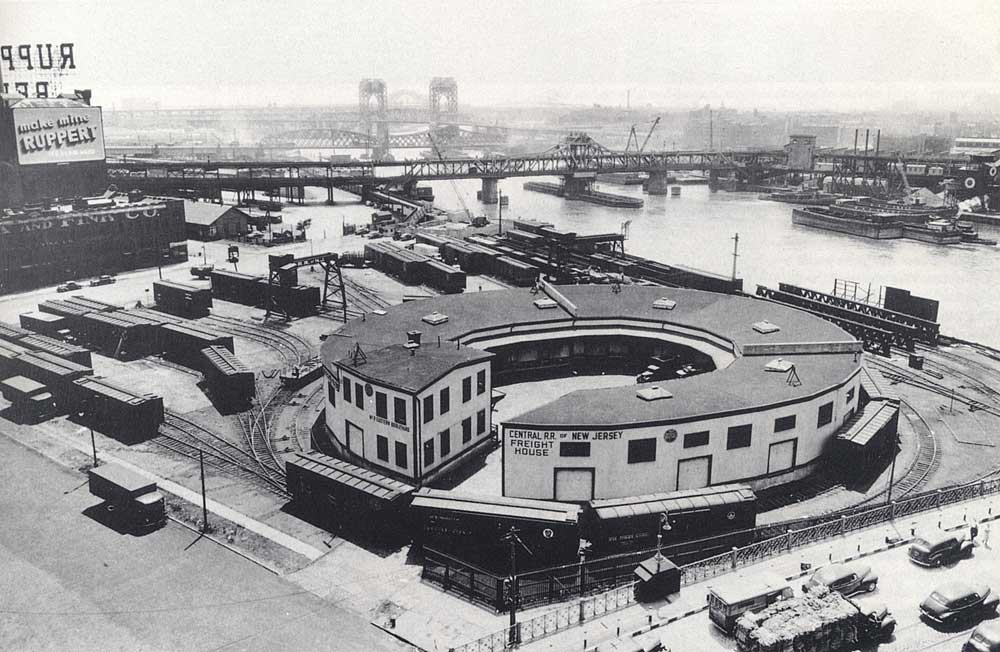 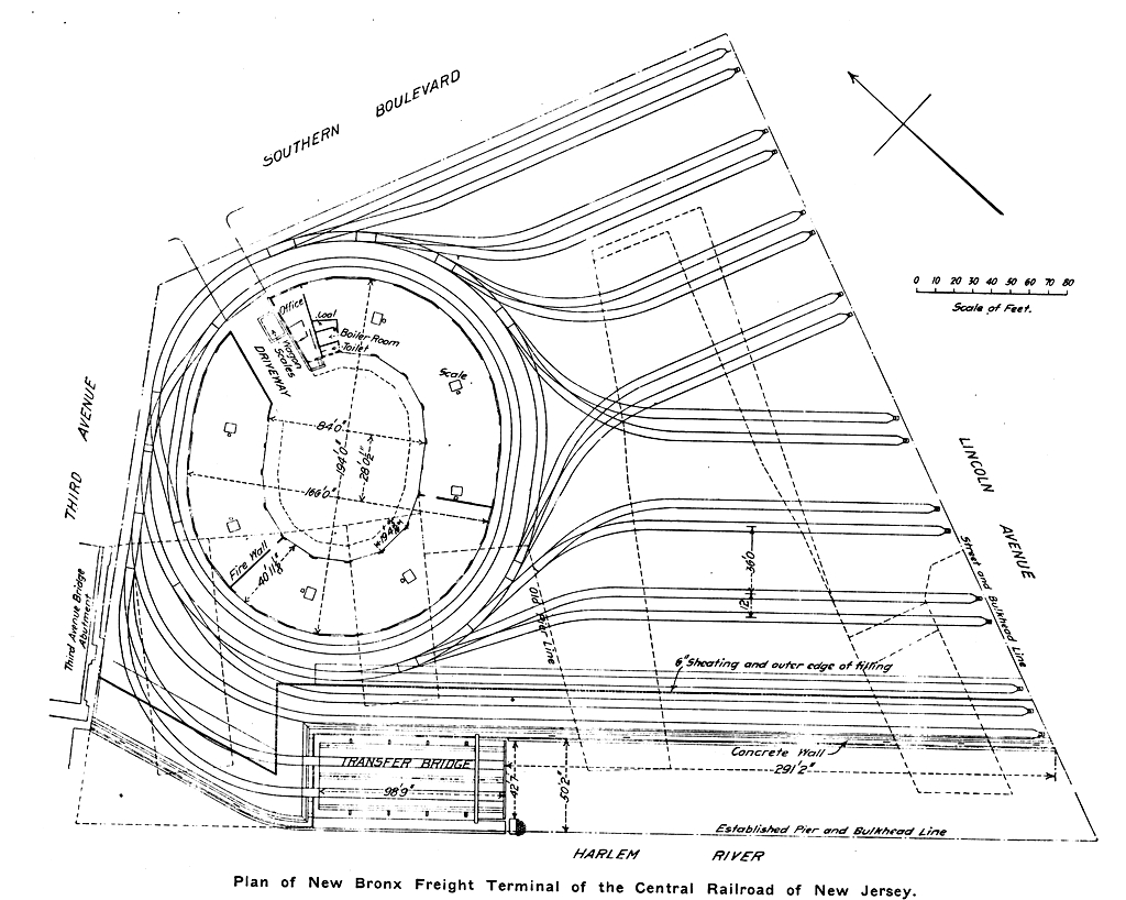 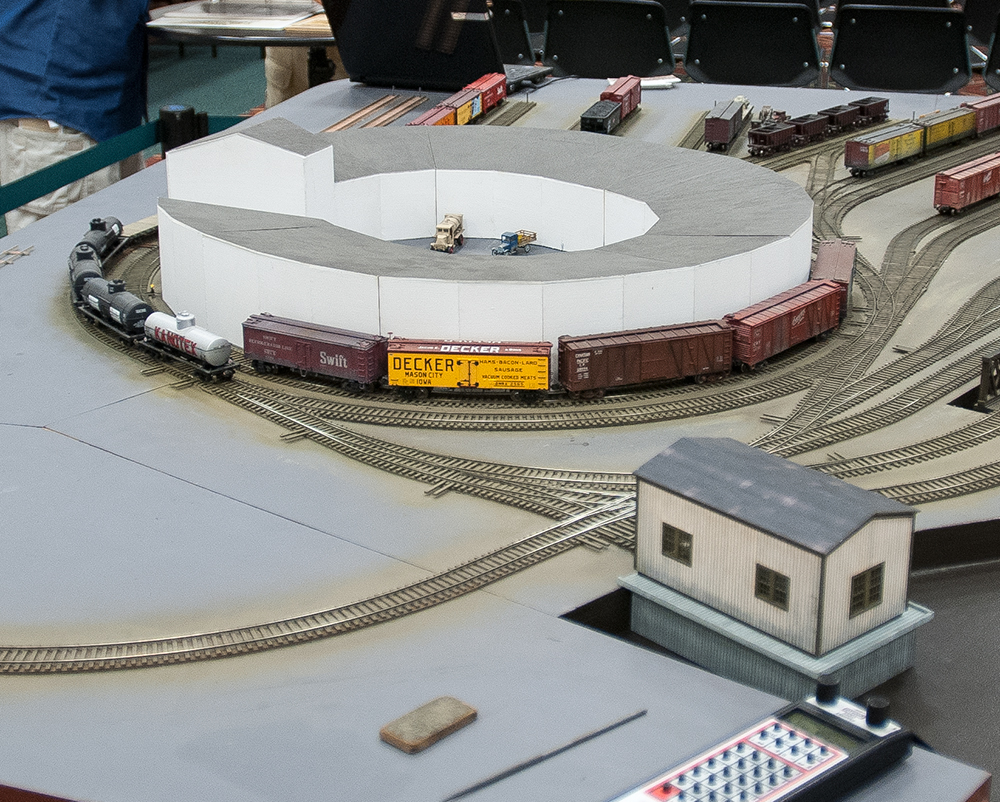 www.bronx-terminal.com/?p=93 www.bronx-terminal.com/?p=93The trackwork this guy built is really impressive. 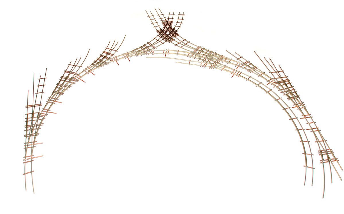 |
|
|
|
Post by prr 4467 on Mar 25, 2024 8:58:51 GMT -8
While I could agree with much of that above, the question that remains is this:
Who in this day generally wants to limit themselves to 40' maximum car length? My whole life most customers or modelers want some car lengths to exceed 40' lengths.
I have a new coworker who is interested in making a SEPTA themed layout. He's been asking me about minimum radius and I've been recommending to try to stay above 15" minimum radius. I did just a week or two ago give him Armstrong's book.
|
|
|
|
Post by prr 4467 on Mar 25, 2024 9:08:49 GMT -8
I'm not trying to be argumentative. My business entails finding acceptable or realistic real world design guidelines on projects and then sticking to them, for good reasons. Sometimes you do have to explain or teach the client.
I wish that I had one dollar for each and every single time I've been standing in a train store, either as the sales person or just as one of the usual suspects that hangout on Saturdays, and had to have the conversation about why someone cannot run a Union Pacific Big Boy on 18" radius curves. You try to explain it factually using real math and they often do not get it at all and then make statements like "it's bs the manufacturer doesn't make a Big Boy able to go around my 18" radius curves". Explaining clearances and parts getting in the way just doesn't cut it for these individuals, and there are more of them out there than you would ever believe.
Most of the regulars on here are way more knowledgeable, but it's easy to forget that Armstrong was writing in a time when too many people were not thinking about the trackwork they were creating, and he was attempting to provide guidelines that would provide excellent bullet-proof operation. Yes, you can sometimes go below those guidelines and get away with it, but sometimes not, as I have found out.
|
|
|
|
Post by Baikal on Mar 25, 2024 9:21:29 GMT -8
While I could agree with much of that above, the question that remains is this: Who in this day generally wants to limit themselves to 40' maximum car length? My whole life most customers or modelers want some car lengths to exceed 40' lengths. I have a new coworker who is interested in making a SEPTA themed layout. He's been asking me about minimum radius and I've been recommending to try to stay above 15" minimum radius. I did just a week or two ago give him Armstrong's book.
If you'd said only 40 or 50 ft cars, I'd say there are still a lot of modelers in this day that don't operate any longer freight cars. Or very rarely.
Modeling the early 1950s, still a popular "steam to diesel transition era", the vast majority of cars were 40 ft with cars over 50 ft being rare. Tank cars and covered hoppers were ususally less than 40 ft. Through the 1960s industry doors were typically spaced for 40 or 50 ft cars, so longer house cars didn't become popular until the shift to intermodal. Exceptions being special service cars like auto parts, mill gondolas... |
|
|
|
Post by Baikal on Mar 25, 2024 9:40:52 GMT -8
Cajon Pass had at one time 11-degree prototype curves, which I believe were subsequently improved. A 10-degree prototype railroad curve has a radius of 572.65'. The current railroad design guidelines do not recommend anything over 10-degree mainline curves. In the model world it is essential to test trackwork before finalizing. The vertical kinks shown in the example above are really not equivalent to a calculated vertical curve length and most assuredly will cause problems with the 86' cars. It is often the combination of horizontal and vertical curvature with superelevation in the model world that causes the issues. Seldom do we have the ideal horizontal curve without also vertical curvature of some type at the same location. That is where problems creep in and I believe that is why Armstrong offered the general guidelines that he did in his book. (I still buy the book and give it to newbies.) Also, Tangent has several different versions of draft gear on these cars, so what will work depends on which cars are actually coupled to each other. This is specifically because some have better coupler lateral swing than others. The one post above appears to say that a modeler wants to have 12" radius curves on HO industrial track. My answer to that is absolutely no way. It is just asking for problems. In my personal experience with the Tangent 86' boxcars, I did have to relay portions of my layout to make them work. The perfect flat horizontal curves with no superelevation on them at all and no vertical kinks anywhere were adequate at 26" horizontal curve radius. Other areas where there is actually superelevation had to be 28" or 30" radius to work for me, and it is the short tangent distance between reverse curves that becomes a problem with the Tangent cars in particular. Anything less than a 6" tangent section between curves of 28" or 30" radius is not enough. The sway of the cars will tend to make some of them derail when coupled in multiples. I would think that any crossover having less than an 8" effective tangent distance could be a challenge for these cars to navigate. Crossovers are always simple curve radius which means there is no easement whatsoever to counteract the side-to-side yaw or sway effect that happens when a train moves through them. That's why in the prototype world #8 turnouts are nearly unheard of in mainline situations. Instead they are up around #20 or longer.
Why "absolutely no way" to 12" radius curves when such curves exist (yes rare) on the prototype?
What are these "railroad design guidelines" you speak of? Link? Because, like I've already written, a railroad is going to use the largest possible radius considering all factors like land available & costs, development costs, operating costs / savings vs other alignments, etc. If a 450 ft radius curve or less works best, that's what's going to be used. Because railroad economics. Been there done that not only on the ground as a conductor but as Calif Dept of Transportation tech advisor (track & signal capital projects) to the LOSSAN Rail Corridor Agency (2nd busiest pax corridor in the US) for 9 years. Involved in many track improvement projects inc curve-reduction.
I also reccomend modelers use the largest possible radius for the same reasons (esp real estate "costs"). Long model RR equipment on tight curves, even though it might be engineered to operate, may look rediculous like a Big Boy on 24" curves- which was not possible on the prototype. But 50 ft cars in an industrial area no problem.
|
|
|
|
Post by cemr5396 on Mar 25, 2024 9:58:10 GMT -8
to expand on the bit about freight car lenghts, min radius is very much dependent on what kind of cars you need to run. For obvious reasons. And yes, transition era modelers have this easier than modern modelers like myself.
At my club, we take a "run what you brung" approach to running trains so you really get a contrast of different equipment. A friend of mine runs transition era stuff and I model the present day (ish), we could both be running a 30 car mixed freight but mine is AT LEAST 1/3rd longer due to the fact that he runs nothing over 60 feet (his longest car is a 57' boxcar), while a fairly healthy chunk of my trains are comprised of cars that are over that length.
the sharpest curve on the layout (that is not an industrial track) is a 22" curve exiting the staging yard, but importantly, there is NO reverse curve there. It's a tangent track, the curve, and then another tangent, both of which are several feet long. We've never found anything that will not run on it, including 89 and 85 foot autoracks and pig flats. I've even done 'long-shorts' with an auto rack and a short 2 bay hopper coupled together and had no issues. The caveat to that, is both cars I used in that experiment were Walthers, so they don't exactly have scale sized draft gear. However, the auto rack has had it's swinging draft gear fixed in place so that obviously limits its ability to negotiate sharp curves somewhat.
|
|
|
|
Post by jonklein611 on Mar 25, 2024 10:12:32 GMT -8
to expand on the bit about freight car lenghts, min radius is very much dependent on what kind of cars you need to run. For obvious reasons. And yes, transition era modelers have this easier than modern modelers like myself. At my club, we take a "run what you brung" approach to running trains so you really get a contrast of different equipment. A friend of mine runs transition era stuff and I model the present day (ish), we could both be running a 30 car mixed freight but mine is AT LEAST 1/3rd longer due to the fact that he runs nothing over 60 feet (his longest car is a 57' boxcar), while a fairly healthy chunk of my trains are comprised of cars that are over that length. the sharpest curve on the layout (that is not an industrial track) is a 22" curve exiting the staging yard, but importantly, there is NO reverse curve there. It's a tangent track, the curve, and then another tangent, both of which are several feet long. We've never found anything that will not run on it, including 89 and 85 foot autoracks and pig flats. I've even done 'long-shorts' with an auto rack and a short 2 bay hopper coupled together and had no issues. The caveat to that, is both cars I used in that experiment were Walthers, so they don't exactly have scale sized draft gear. However, the auto rack has had it's swinging draft gear fixed in place so that obviously limits its ability to negotiate sharp curves somewhat. Well said. Easements can also improve performance for singular type curves like this. |
|
|
|
Post by Baikal on Mar 25, 2024 10:31:43 GMT -8
The one post above appears to say that a modeler wants to have 12" radius curves on HO industrial track. My answer to that is absolutely no way. It is just asking for problems. Industrial with smaller cars did some incredible stuff: www.bronx-terminal.com/?p=93The trackwork this guy built is really impressive.
Every time I see those NYC area carfloat operations and the track models I'm blown away. And there were numerous examples around the waterfront, esp pre-WW2, the result of high land costs squeezing the railroads into the smallest footprint possible.
Note that the track that looks like it's entering the little building had to use hand-placed "jumper" rails to get over the switch points of the track it's crossing. No room for frogs.
|
|
|
|
Post by lvrr325 on Mar 26, 2024 0:42:27 GMT -8
FWIW, 158" radius would result in a 180' curve 26'4" wide. 85" radius would be a touch over 14 feet wide. 30" gets you five feet, which results in a practical size for most HO layouts.
|
|
|
|
Post by 12bridge on Mar 26, 2024 6:22:43 GMT -8
Cars, especially big ones (Tangent 86'ers) with scale/semi scale coupler boxes really hate reverse curves of any kind, especially if they are next to each other. Some of those 86' cars have a flared box, and some do not depending on which version it is, and it totally changes their operating characteristics.
I loved the concept of the Micro Engineering yard ladder system, so we used it downstairs, but I would never use it again and can not wait to be rid of it. It does not play well all the time with certain cars.
Side note - Bush Terminal RR in Brooklyn would have to reject cars often for wheels hitting the frames on certain curves. Industrial railroads also used coupler extensions to get around this issue as cars got bigger and draft gears did not have the swing.
|
|
|
|
Post by packer on Mar 26, 2024 6:53:34 GMT -8
I loved the concept of the Micro Engineering yard ladder system, so we used it downstairs, but I would never use it again and can not wait to be rid of it. It does not play well all the time with certain cars. Side note - Bush Terminal RR in Brooklyn would have to reject cars often for wheels hitting the frames on certain curves. Industrial railroads also used coupler extensions to get around this issue as cars got bigger and draft gears did not have the swing. I'm guessing the yard ladder system doesn't play well with 85'+ cars? any experience with 63' or so cars or is it more of a car dependent thing? I'm curious what the coupler extension looks like. |
|
|
|
Post by 12bridge on Mar 26, 2024 6:56:51 GMT -8
|
|
|
|
Post by riogrande on Mar 26, 2024 8:36:58 GMT -8
Tried to add a photo, but the site says an iPhone file is too big If you use a photo host, you should be able to display photos in posts here. |
|
|
|
Post by prr 4467 on Mar 26, 2024 8:47:40 GMT -8
Cajon Pass had at one time 11-degree prototype curves, which I believe were subsequently improved. A 10-degree prototype railroad curve has a radius of 572.65'. The current railroad design guidelines do not recommend anything over 10-degree mainline curves. In the model world it is essential to test trackwork before finalizing. The vertical kinks shown in the example above are really not equivalent to a calculated vertical curve length and most assuredly will cause problems with the 86' cars. It is often the combination of horizontal and vertical curvature with superelevation in the model world that causes the issues. Seldom do we have the ideal horizontal curve without also vertical curvature of some type at the same location. That is where problems creep in and I believe that is why Armstrong offered the general guidelines that he did in his book. (I still buy the book and give it to newbies.) Also, Tangent has several different versions of draft gear on these cars, so what will work depends on which cars are actually coupled to each other. This is specifically because some have better coupler lateral swing than others. The one post above appears to say that a modeler wants to have 12" radius curves on HO industrial track. My answer to that is absolutely no way. It is just asking for problems. In my personal experience with the Tangent 86' boxcars, I did have to relay portions of my layout to make them work. The perfect flat horizontal curves with no superelevation on them at all and no vertical kinks anywhere were adequate at 26" horizontal curve radius. Other areas where there is actually superelevation had to be 28" or 30" radius to work for me, and it is the short tangent distance between reverse curves that becomes a problem with the Tangent cars in particular. Anything less than a 6" tangent section between curves of 28" or 30" radius is not enough. The sway of the cars will tend to make some of them derail when coupled in multiples. I would think that any crossover having less than an 8" effective tangent distance could be a challenge for these cars to navigate. Crossovers are always simple curve radius which means there is no easement whatsoever to counteract the side-to-side yaw or sway effect that happens when a train moves through them. That's why in the prototype world #8 turnouts are nearly unheard of in mainline situations. Instead they are up around #20 or longer.
Why "absolutely no way" to 12" radius curves when such curves exist (yes rare) on the prototype?
What are these "railroad design guidelines" you speak of? Link? Because, like I've already written, a railroad is going to use the largest possible radius considering all factors like land available & costs, development costs, operating costs / savings vs other alignments, etc. If a 450 ft radius curve or less works best, that's what's going to be used. Because railroad economics. Been there done that not only on the ground as a conductor but as Calif Dept of Transportation tech advisor (track & signal capital projects) to the LOSSAN Rail Corridor Agency (2nd busiest pax corridor in the US) for 9 years. Involved in many track improvement projects inc curve-reduction.
I also reccomend modelers use the largest possible radius for the same reasons (esp real estate "costs"). Long model RR equipment on tight curves, even though it might be engineered to operate, may look rediculous like a Big Boy on 24" curves- which was not possible on the prototype. But 50 ft cars in an industrial area no problem.
1. Just because you CAN do it does not mean you SHOULD. Going BELOW recommended design guidelines means safety is compromised, which in the model world means wrecks can occur. Maybe you don't care about wrecks, but I do because I don't like damaging my equipment. For over 45 years, I've never once heard anyone working in a model train store, whether myself or other people I've known, recommend using anything below 15" minimum radius. Believe me customers ask this all the time, and we TRY to talk them out of it. 2. Some years ago I searched online, found and downloaded the BNSF actual track design standards for FREIGHT trains not lighweight passenger rail. There also are AREMA (national) design standards that are very comparable. They DO NOT recommend construction of any NEW mainline curves over 10 degrees (572.65' real world radius) for GOOD reasons. Specifically, in 1968, Santa Fe found that empty autoracks on the head ends of trains derailed far too often on Cajon Pass. They alleviated this by lowering the profile grade at Summit by a couple hundred feet while at the same time shifting the horizontal alignment (and presumably superelevation) to LESSEN the radius, I believe to 10-degrees of curvature or better. In the REAL world just because a 450' radius COULD work does not mean it will get built. Professional engineers have to allow a safety factor for things that may occur. We can be sued and lose our livelihood if we make mistakes. 3. As someone who has worked in retail model train sales, I know beyond the shadow of a doubt that most customers are going to eventually want bigger than 50' freight cars on their layouts. This is WHY I've spent a lot of time convincing them to go to as large a radius as possible--because I know they will go there anyway. I was a kid once, too. No kid today who sees common 60', 86', and 92' length cars in real life will ever be happy with curves designed for 40' or even 50' cars. He or she just will not. Whether you build it or not, they will come. 4. The client and/or the track maintenance supervisor can build whatever they want. The professional engineer's job is to document what is recommended, so that we have documentation of what and why it was recommended, because again, we can and do get sued and all too often, and we have to be able to prove what was originally recommended to the client in court. My college best friend was sued and did win. He also went back to school and became an attorney, now working for the City of Las Vegas on engineering related court cases. |
|
|
|
Post by Baikal on Mar 26, 2024 13:07:21 GMT -8
Why "absolutely no way" to 12" radius curves when such curves exist (yes rare) on the prototype?
What are these "railroad design guidelines" you speak of? Link? Because, like I've already written, a railroad is going to use the largest possible radius considering all factors like land available & costs, development costs, operating costs / savings vs other alignments, etc. If a 450 ft radius curve or less works best, that's what's going to be used. Because railroad economics. Been there done that not only on the ground as a conductor but as Calif Dept of Transportation tech advisor (track & signal capital projects) to the LOSSAN Rail Corridor Agency (2nd busiest pax corridor in the US) for 9 years. Involved in many track improvement projects inc curve-reduction.
I also reccomend modelers use the largest possible radius for the same reasons (esp real estate "costs"). Long model RR equipment on tight curves, even though it might be engineered to operate, may look rediculous like a Big Boy on 24" curves- which was not possible on the prototype. But 50 ft cars in an industrial area no problem.
1. Just because you CAN do it does not mean you SHOULD. Going BELOW recommended design guidelines means safety is compromised, which in the model world means wrecks can occur. Maybe you don't care about wrecks, but I do because I don't like damaging my equipment. For over 45 years, I've never once heard anyone working in a model train store, whether myself or other people I've known, recommend using anything below 15" minimum radius. Believe me customers ask this all the time, and we TRY to talk them out of it. 2. Some years ago I searched online, found and downloaded the BNSF actual track design standards for FREIGHT trains not lighweight passenger rail. There also are AREMA (national) design standards that are very comparable. They DO NOT allow construction of any NEW mainline curves over 10 degrees (572.65' real world radius) for GOOD reasons. Specifically, in 1968, Santa Fe found that empty autoracks on the head ends of trains derailed far too often on Cajon Pass. They alleviated this by lowering the profile grade at Summit by a couple hundred feet while at the same time shifting the horizontal alignment (and presumably superelevation) to LESSEN the radius, I believe to 10-degrees of curvature or better. In the REAL world just because a 450' radius COULD work does not mean it will get built. Professional engineers have to allow a safety factor for things that may occur. We can be sued and lose our livelihood if we make mistakes. 3. As someone who has worked in retail model train sales, I know beyond the shadow of a doubt that most customers are going to eventually want bigger than 50' freight cars on their layouts. This is WHY I've spent a lot of time convincing them to go to as large a radius as possible--because I know they will go there anyway. I was a kid once, too. No kid today who sees common 60', 86', and 92' length cars in real life will ever be happy with curves designed for 40' or even 50' cars. He or she just will not. Whether you build it or not, they will come.
(Ed, who started this thread is involved in Free-mo where this subject is being actively discussed on several sites re: industry module standards "a work in progress")
Ans 1. I'm figuring that very few people will want to build modules with an INDUSTRY TRACK of less than say, 18 or 24 inch radius. And I'm talking about the industry track that serves the customer, not a THROUGH TRACK or LEAD. But since the prototype does have industry track curves down to 12" HO scale radius (many more in the past, but people do model the past) why ban it? I'm not mandating the use of sharp curves, I'm just saying acknowlege they exist on the prototype and model them accordingly. Which is rarely. I wrote above and will reiterate here "I also recommend modelers use the largest possible radius for the same reasons (esp real estate "costs"). Long model RR equipment on tight curves, even though it might be engineered to operate, may look rediculous like a Big Boy on 24" curves- which was not possible on the prototype."
Ans 2. I asked for a link for the source of your "The current railroad design guidelines do not recommend anything over 10-degree mainline curves.", did not receive it. Do you have the link to some official org with that literal recommendation? I'm not saying it doesn't exist, but I'd like a copy for my RR operations files. I'll point out again that railroads design trackage to maximize value, which is benefit divided by cost where cost is in $ or $ per some unit. If a tight curve makes more sense (or is the only physical alternative) guess what, a tight curve is going in.
What do you mean by "mainline"? That's a loose term that can mean different things to different people, it's fuzzy. However MAIN TRACK is defined by rule and has nothing to with curves or speed. There is no railroad rule that says Main Track (or "mainline" for that matter) has to fall between some minimum or maximum radius. Some Main Track curves are sharp enough to require Restricted Speed. (See examples below)
Ans 3. You wrote "No kid today who sees common 60', 86', and 92' length cars in real life will ever be happy with curves designed for 40' or even 50' cars." That's a bold statement. I was just reading about some young person that jumped into HO narrow gauge, where 28 ft cars rule. I'm pretty sure there are some younger "kids" with modules who's focus is something other than modern long cars that go from intermodal terminal to intermodal termanal behind GEVOs. What are people going to run behind those Rapido FTs? The April RMC cover story is about Civil War railroading.
You wrote "In the REAL world just because a 450' radius COULD work does not mean it will get built."
Off the top of my head here's some real world examples of sub-450 ft trackage serving different functions. The builders knew what they were doing. All in the L.A. Area:
UP Main Track - West Colton loop. 20+ long trains per day? A larger loop would have been more expensive (land, etc), but would not have added much value. It still would have been restricted speed. Built approx 1967? Approx 380 ft. radius. 34.067276, -117.345782 (insert into a Google Maps search)
Connector UP East Yard - BNSF Hobart Yard at Hobart Tower. 100s of cars transfered each way daily during 1980s. Don't know about now, but it's still active. I worked over these rails many times. How else ya gonna connect the two big yards? Approx 350 ft radius. 34.011770, -118.204695
Industy Lead UPRR. End of Track was once UP's main Los Angeles team track yard with 10 or 12 tracks, cranes, plus other industries. A lot of cars passed over these tracks for about 100 years. I worked here too. Approx 380 ft radius. 34.018728, -118.233097
Former UP/SP branch (Main Track). Abandoned 15(?) years ago but used to host 4-8 trains per day, including long flats. Approx 390 ft. 33.963962, -118.085462
Plus all the industry trackage that's under 450 ft, some built in the last 20 years.
On the other hand here's a very broad former ATSF Main Track curve, now under construction for light rail. It was built big (no effect on speed) because it was appropriate. Appropriate for the place (cheap land unlike now) and time. Approx one mile radius. 34.110451, -117.822456 |
|
|
|
Post by Baikal on Mar 26, 2024 13:11:32 GMT -8
Side note - Bush Terminal RR in Brooklyn would have to reject cars often for wheels hitting the frames on certain curves. Industrial railroads also used coupler extensions to get around this issue as cars got bigger and draft gears did not have the swing.
Or even chains when couplers wouldn't mate. The Pacific Electric had freight cars (50? 100?) built to SP standards but with brake & other underframe equipment modified for tight curves & street running. PE was the 2nd largest freight carrier in southern California, ahead of Santa Fe and UP.
|
|
|
|
Post by Colin 't Hart on Mar 26, 2024 13:25:59 GMT -8
|
|
|
|
Post by Baikal on Mar 26, 2024 13:37:04 GMT -8
I don't even have to click on the map link. A classic from Portland!
Nice because you can look down on the operations from MAX trains on the Steel Bridge. |
|
|
|
Post by Colin 't Hart on Mar 26, 2024 13:38:56 GMT -8
I don't even have to click on the map link. A classic from Portland! Nice because you can look down on the operations from MAX trains on the Steel Bridge. Soon to be consigned to the annals of history, it seems. |
|
|
|
Post by wagnersteve on Mar 26, 2024 13:59:13 GMT -8
3/26/2024, 5:52 p.m., EDT
Aha! Colin, you mean the Portland in Oregon. I've been there more than once but know Portland, Maine better. The one in Oregon was named after it because a man who grew up in Maine won a coin flip with a man from Boston who wanted the place name for his home town. Historian Stewart Holbrook was involved in an unsuccessful effort to get the name of the city in Oregon changed back to Multomah, which is what the indigenous people had called it; that failed. But that's the name of the Oregon county that includes Portland.
|
|
|
|
Post by Baikal on Mar 26, 2024 14:34:11 GMT -8
3/26/2024, 5:52 p.m., EDT Aha! Colin, you mean the Portland in Oregon. I've been there more than once but know Portland, Maine better. The one in Oregon was named after it because a man who grew up in Maine won a coin flip with a man from Boston who wanted the place name for his home town. Historian Stewart Holbrook was involved in an unsuccessful effort to get the name of the city in Oregon changed back to Multomah, which is what the indigenous people had called it; that failed. But that's the name of the Oregon county that includes Portland.
Close. But Portland Oregon is in three counties: Clackamas, Multnomah, and Washington. There is no Portland County.
Strangely(?) I lived and worked in both Portlands doing railroad or rail transport work at different times. Ok South Portland, Maine, close.
Portland, OR was nice. You could ride light rail or transit buses without the criminal element that's so common now. Brewpubs were just taking off... coffee coffee coffee. Still physically beautiful but it's the people who make the place. The comedy sketch series "Portlandia" nails the way it was. Whenever it's on I'm always pointing out to my wife "IT WAS JUST LIKE THAT!". Portland OR in the early '90s was sort of like San Francisco in the late 60s which is also wrecked, and by the same sorts, same stuff. It was preventable.
There was a lot of street-running in Portland OR and East Portrland. SP, UP, SP&S, GN, NP, Portland Treminal. The SP&S Historical Society magazine had an article about SP&S's urban branch (12th St?) that ran out of the Hoyt St Yard area. 18 mos, 2 years ago? I should get it out of storage & re-read. There are curves around NW Portland streets where the track has to curve left before making a 90 deg right turn. Plus some low hills.
Portland, ME is pretty nice, a walkable downtown & port. Safer than PDX or SFO but now has some of the drug problems and high unemployment. But what US city doesn't. I didn't spend much time in the city proper, was working too much. It also had some cool old street running in brick streets. Also a Portland Terminal railroad. Mainers are "different" and you'll never fit in if you aren't from there. Better than Massholes tho. A lot of same people who settled New England migrated directly west across America and settled the Pacific Northwest. More or less. Mainers are more similar to Oregonians than they are to Virginians.
|
|
|
|
Post by 12bridge on Mar 26, 2024 14:57:28 GMT -8
Since we are getting into tolerances and stuff here..
What most modelers also fail to realize is just how much freight cars move that is not portrayed in models at all. Springs, side bearings, track conditions (a whole different story and list of issues too...), couplers binding, wheelsets rubbing floors, the list goes on.
As cars keep getting bigger, the track follows. We have a #8 turnout for a customer, and its absolutely at its limit for 72' reefers. Throw in cars without long drawbars and it makes for some interesting nights.
|
|
|
|
Post by edwardsutorik on Mar 26, 2024 15:06:56 GMT -8
I've got a Free-mo module in mind, with industry on each side of a double track main. Anywhere where a long car might go, and that includes a mini-yard, will get #8 switches. All other industrial switches will be #6. There's no curved track worth mentioning (being a long narrow straight thing), so curve radius doesn't matter much.
There'll be some HOn22 (Z scale track) for some steel ingot car tracks--THAT'S looking to be around 9" or less.
Ed
|
|
|
|
Post by riogrande on Mar 26, 2024 15:13:41 GMT -8
I put in a #8 turnout for the siding where the 89' TOFC flatcars will be parked.
|
|
|
|
Post by Baikal on Mar 26, 2024 16:33:44 GMT -8
I've got a Free-mo module in mind, with industry on each side of a double track main. Anywhere where a long car might go, and that includes a mini-yard, will get #8 switches. All other industrial switches will be #6. There's no curved track worth mentioning (being a long narrow straight thing), so curve radius doesn't matter much. There'll be some HOn22 (Z scale track) for some steel ingot car tracks--THAT'S looking to be around 9" or less. Ed
Awesome. A "regular" Free-mo module with spurs, not an "industry-mo" / "mudmo" then? The HOn22 sounds very cool. Will it be powered, with what? Or static? I'm sure you've seen www.carendt.com/micro-layout-design-gallery/
The Industry-mo concept is interesting, spurring some good discussion over there on io groups for all modules and even non-module layouts.
The definitions and standards need to be worked out. The Free-mo standards need to be complete re-written, now a mess. Others have commented on this.
About industry-mo module trackage. For Free-mo operations ease, there needs to be a way to distinguish the two types of tracks that would make up most of these modules. In the spirit of Prototype Modeling, when possible, prototype nomenclature should be used in outr modeling to minimize confusion. No need to re-invent the wheel.
On real railroads, "industrial trackage" is usually defined by rules in a negative manner. That is, as "track other than Main Track, yard tracks, running tracks..." or similar. Note that Main Track is defined as "track designated by Timetable where train movement is authorized by... ABS, CTC, interlocking..." There is usually no differentation between what Free-mo is calling an "Industry Lead" or "through track" and the tracks where industry spots are located. It's ALL "Industry Trackage" on the prototype. Tracks may have numbers or names. Or known by the business they serve, or by other means.
So what do we call these two types of tracks on the modules? And how are they defined?
I'm for calling the "through track" the "INDUSTRY LEAD". Railroads sometimes refer to this track as "Industry Lead" or similar. "Through Track" is ok. Defined for Free-mo purposes as "track that connects to other modules and/or multiple industries". (draft) It might even have an industry on it where cars will have to be moved to serve industries beyond (rare).
For those tracks serving one or more customers and ususally stubbing-out (but not always. Could be on a double-ended spur or?)... How to designate other than in the negative as "other than Industry Lead". But that's clumsy. (draft). Just "Industry Tracks" per the prototype? I know I do not like calling them "customer tracks" per the current Free-mo standard as they don't always serve "customers". It could be a tail track, a storage track, team track, track used for RR purposes like MOW, etc.
Careful of distinctions between the two types of trackage based on ownership of the land under the tracks. Often it can not be determined visually where RR property and "customer" property begins/ends. And in many areas, the RR or a 3rd party (public agency, shell company, etc) owns the ROW up to the customer door. Almost all industries served by street trackage do not own the tracks / land under the tracks.
|
|
|
|
Post by edwardsutorik on Mar 26, 2024 17:28:58 GMT -8
Awesome. A "regular" Free-mo module with spurs, not an "industry-mo" / "mudmo" then? The HOn22 sounds very cool. Will it be powered, with what? Or static? I'm sure you've seen www.carendt.com/micro-layout-design-gallery/Yup, a regular Free-mo module. It's based on the long straight of the SP going through Berkeley and Emeryville (CA). There'll be a double track main, and an industry lead on each side--4 tracks total. Various industries will come off the leads, including Judson Steel and Del Monte. There'll be Shellmound Tower, and a very small yard on one side. I was gonna have the Sherwin-Williams paint company,  but the guys who make the fancy illuminated roof sign I was gonna use managed to screw it up, so that's out. The idea is to be able to have through trains on the main while folks can do switching off the leads. And, of course, they may have to cross the main at times. Currently, it's planned to be 18' long, but it can be easily extended a very long way. The HOn22 will likely not be powered, but ya never know. It's just going to curve out of the furnace building and go off the side with a turn. As I said, it's just to get the ingots out of the building, over to the rolling mill (which is WAY off the module). It's gonna be a long while before it's done--lotsa work. But I've started the electric arc furnace, and I'm liking it. Ed Edward Sutorik |
|
|
|
Post by grahamline on Mar 26, 2024 21:17:01 GMT -8
|
|
|
|
Post by slowfreight on Mar 27, 2024 6:14:03 GMT -8
Late to the party here, but beyond operational performance, appearance does enter the discussion. I found that if you normally view the curve from the inside, you can go a little sharper and have things look reasonable. Outside curves highlight the toy-like nature of a sharp curve much faster. Thus, whatever your minimum radius would be, aiming to make outside curves larger than that will help trains look better.
|
|


