Deleted
Deleted Member
Posts: 0
|
Post by Deleted on Apr 19, 2014 17:53:59 GMT -8
The long hood is done except for installing the sand fill. It is made out of delrin and will need to be sand blasted, sprayed with adhesion promoter and primer before being put on the model.
|
|
Deleted
Deleted Member
Posts: 0
|
Post by Deleted on Apr 20, 2014 7:02:18 GMT -8
Now its time to look at the sill, pilots and other stuff from the walkway down.
The hardest detailing item is the fuel fills. When built the low nose GP9's came from EMD with a divided fuel tank and dual fuel fills. The forward tank was the smallest and was the fuel mixture SP used to start the locomotive. The rear tank and rear fuel fill was the fuel SP used for operation of the locomotive. From what I can tell and have been told this dual fuel experiment didn't last that long and SP removed the baffle, forward fuel fill and forward fuel pressure gauge.
To model this, I first used some styrene to represent the plated over forward fuel fill. The rear is challenge. But to accomplish the task, I cut the fuel fill and fuel level gauge from a scrap P2K GP9 sill. I then marked sill with the cut out piece using a handrail stanchion hole to line things up. I cut out the portion of the sill to fit the new fill and glued in place. I used some cut down 0.040" styrene to achieve the transitions. Some body putty on the seams and I then drilled out the fuel fill to insert a Details West fuel fill. As built the fuel fill caps are slightly recessed with the face of the sill. But SP's caps protruded from the fuel fill face plate. Think "inny" and "outy" belly buttons!
The fireman's side set up is different and that will shortly follow.
|
|
|
|
Post by tankcarsrule on Apr 20, 2014 14:34:29 GMT -8
A very nice built that requires lots of skill. I look forward to future installments.
Regards, Bobby
|
|
Deleted
Deleted Member
Posts: 0
|
Post by Deleted on Apr 21, 2014 11:14:34 GMT -8
The left or fireman's side is done.
The majority of SP low nose GP9's had access doors above the fuel tank on the left side. I used some styrene sheet and installed Plano etched EMD knuckle buster latches. I removed material on the styrene strip representing the doors so the latches would fit flush. I then used some bits of styrene to finish the skirting.
|
|
|
|
Post by roadkill on Apr 21, 2014 17:06:21 GMT -8
My I make a suggestion about sand fillers? Seems like blasting those little things would be quite an bother, why not get some Atlas SD24 sand fillers? I've bought several packages of the on that evil auction site to use on several future builds including a PC turbo-lobotomized GP20 and several GP30s.
|
|
Deleted
Deleted Member
Posts: 0
|
Post by Deleted on Apr 23, 2014 8:16:24 GMT -8
Got the rear pilot finished.
This is the brown box GP18 with the Athearn blue box style chassis mounted couplers not body. So it has an open pilot under the coupler to allow the shell to be installed on the drive. That is changing to body mounted couplers. I filled the gap with some styrene and used Detail Associates foot board pilots, minus the foot boards. I added the MU signal hose brackets from an Evergreen Models C-channel shape styrene shape cut in half. The cut bars are scratch built. The drop step is a DA part as is the MU plug. The holes for the foot board cut bar is filled as is the two outer holes for the cut bars, which were repositioned due to the use of the AAR type of cut bar.
|
|
Deleted
Deleted Member
Posts: 0
|
Post by Deleted on Apr 24, 2014 18:12:07 GMT -8
Front pilot is finished.
SP removed the foot boards and corresponding MU hose holder and installed a flat plate with two loops to hold the MU signal hoses.
Since the SP GP9 low nose had a lot in common with the GP20, like the step boxes in the front. I used some strip styrene and topped them with some safety tread material from Cannon & Company.
I replaced the too shallow Proto steps with etched steps from Cannon & Company. You can also see my step boxes and how they are built.
|
|
Deleted
Deleted Member
Posts: 0
|
Post by Deleted on Apr 25, 2014 9:13:17 GMT -8
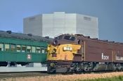
Ready for some scarlet and gray!
|
|
|
|
Post by onequiknova on Apr 25, 2014 13:03:38 GMT -8
Are the two dome topped 48" fans the old Proto fan? I need a set of those fans, but from what I can tell, nobody makes them. I would love a Cannon version. The RI had those fans on their GP18's and some GP9's.
|
|
Deleted
Deleted Member
Posts: 0
|
Post by Deleted on Apr 25, 2014 13:30:30 GMT -8
Are the two dome topped 48" fans the old Proto fan? I need a set of those fans, but from what I can tell, nobody makes them. I would love a Cannon version. The RI had those fans on their GP18's and some GP9's. Those two fans came from a P2K GP20 that I parted out for.....parts! The nose and dynamic brake housing came from the same GP20. The GP18 comes with a shrouded fan. The SP didn't care much for where a fan came from, just as long as it worked and fit. Elizabeth Allen on her scratch built SP SDP45, choose the SDP that had at one time FIVE DIFFERENT STYLES of 48" fans. Some of SP's maintenance practices were....interesting...... |
|
|
|
Post by railthunder on Apr 26, 2014 19:31:52 GMT -8
Got the rear pilot finished. This is the brown box GP18 with the Athearn blue box style chassis mounted couplers not body. So it has an open pilot under the coupler to allow the shell to be installed on the drive. That is changing to body mounted couplers. I filled the gap with some styrene and used Detail Associates foot board pilots, minus the foot boards. I added the MU signal hose brackets from an Evergreen Models C-channel shape styrene shape cut in half. The cut bars are scratch built. The drop step is a DA part as is the MU plug. The holes for the foot board cut bar is filled as is the two outer holes for the cut bars, which were repositioned due to the use of the AAR type of cut bar.   This is an interesting SP project and thanks for sharing your pictures. Did the Espee put the eyelet for the cut levers to the outside of the square on the cut levers on all of their fleet or just the unit you are modeling? I've not seen that on the prototype before as typically they were mounted to the inside. |
|
Deleted
Deleted Member
Posts: 0
|
Post by Deleted on Apr 26, 2014 20:20:59 GMT -8
This is an interesting SP project and thanks for sharing your pictures. Did the Espee put the eyelet for the cut levers to the outside of the square on the cut levers on all of their fleet or just the unit you are modeling? I've not seen that on the prototype before as typically they were mounted to the inside. All the modernized SP GP9's had the bracket mounted on the outside of the AAR loop. |
|
|
|
Post by railthunder on Apr 27, 2014 8:32:23 GMT -8
I think I asked the wrong question. The eye that holds the pin lifter is on the outside of the top loop but you bent the bottom part of the pin-lifter (where you pull it from the ground) towards the outside of the eye (step side). It should be bent to the inside of the eye (coupler side) from the photos I've seen. I'm by no means an expert, but it appears the bending pattern around the mounting eye is the same as on all later production EMD’s.
SP probably bought these as aftermarket parts when footboards went away I would presume.
|
|
bigzmn
Junior Member

Posts: 91
|
Post by bigzmn on Apr 30, 2014 9:02:20 GMT -8
|
|
|
|
Post by Judge Doom on Apr 30, 2014 20:41:31 GMT -8
Well, not exactly like that... Rule #1, always work off images of the prototype unit you're doing. Things like cut levers, horn locations, etc are subject to change over time. The loops appear to be on the outside of this particular prototype: www.sdrm.org/roster/diesel/d-3709/ |
|
bigzmn
Junior Member
Posts: 91
|
Post by bigzmn on Apr 30, 2014 21:42:59 GMT -8
Well, not exactly like that... Rule #1, always work off images of the prototype unit you're doing. Things like cut levers, horn locations, etc are subject to change over time. The loops appear to be on the outside of this particular prototype: www.sdrm.org/roster/diesel/d-3709/This picture shows the cut levers the same as the pix I show. The bend goes inward where on his model the bend goes outward. Chris Z. |
|
|
|
Post by Judge Doom on May 1, 2014 4:38:12 GMT -8
Well, not exactly like that... Rule #1, always work off images of the prototype unit you're doing. Things like cut levers, horn locations, etc are subject to change over time. The loops appear to be on the outside of this particular prototype: www.sdrm.org/roster/diesel/d-3709/This picture shows the cut levers the same as the pix I show. The bend goes inward where on his model the bend goes outward. Chris Z. Although not quite identical, notice the mounting is different: the cut lever loops are on the outside of the two corner mounts they hinge on, instead of in the middle before the lower bends like in your links. |
|
Deleted
Deleted Member
Posts: 0
|
Post by Deleted on May 1, 2014 7:53:42 GMT -8
First, I blindly followed the Detail Associates commercial part. Second, from the photos of SP #3708 which I was using, it was very difficult to see that the bend and placement of the bracket would be different from the DA part. Now, I see it, after spending considerable time studying one photo, but it is still difficult.
I had been using the photos of the #3709 in its Army paint for many of the details, such as lift rings, etc.. But, when it comes to the front pilot, there are changes from some of the last recorded photos of it in SP paint.
|
|
Deleted
Deleted Member
Posts: 0
|
Post by Deleted on May 6, 2014 12:36:10 GMT -8
|
|
|
|
Post by roadkill on May 6, 2014 16:54:54 GMT -8
Nice!
|
|
|
|
Post by stevef45 on May 6, 2014 17:01:03 GMT -8
Jim, awesome work!!
|
|
071
New Member
Posts: 47
|
Post by 071 on May 7, 2014 0:57:58 GMT -8
Stunning as ever!
|
|
|
|
Post by slowfreight on May 7, 2014 9:37:42 GMT -8
For such an old-school model, you cleaned it up very nicely! As well as the nose lighting package turned out, I really like the ex-lighting package details on the long hood. And the Plano parts definitely made a difference. I'd like to see this with some light weathering...a little powders on the underframe and just enough dilute oils to bring out the louvers, seams, and latches in the hood doors. Ready to try it?
|
|
|
|
Post by TBird1958 on May 7, 2014 12:38:31 GMT -8
Great model Jim! Nicely done.
|
|
|
|
Post by buffalobill on May 7, 2014 13:34:17 GMT -8
Jim: Outstanding model, great execution. Light weathering, come on, this is sloppy Pacific. If its weathered it needs to be a rust bucket, unless its fresh from Sacramento.
Now if only you could get your pictures back.
Bill
|
|