|
|
Post by thebessemerkid on Oct 9, 2014 21:13:37 GMT -8
Not trying to spam the thread, just tossing out some pictures for perspective. The Bowser unit looks high, but the prototypes were higher than normal also. Here's a good shot showing fuel tank profile (and all the blocking needed with old tender trucks) 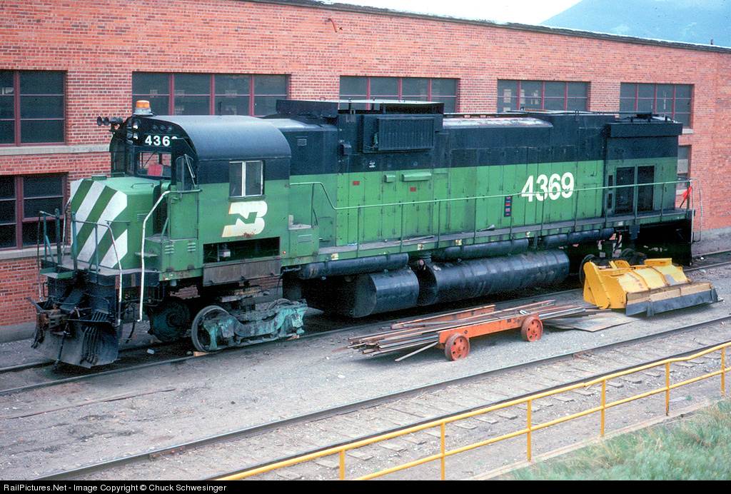 Definitely higher than a trimount C630  |
|
|
|
Post by thebessemerkid on Oct 9, 2014 21:38:33 GMT -8
636's easy to pick out in lineup  636 and a GP (38?)  |
|
|
|
Post by thebessemerkid on Oct 9, 2014 22:38:22 GMT -8
Centuries 630 - 628 - 636  C636 - U25B.  A 636 with F-units and other EMD hood units. Note the frame heights throughout the consist:  |
|
|
|
Post by Judge Doom on Oct 9, 2014 23:12:13 GMT -8
Why are they shoving the 21 pin set up down our throats? Also, my retailer told me today that the non sound versions will spin their wheels in a stall. The Loksound versions all stalled and the wheels stopped turning. Unknown if this is just a matter of altering decoder settings or what. Be warned. Dave That's what a lot of decoder and model manufacturers are moving to now, a big part is allowing more functions than being limited to say just 6. Fully lit front and rear class lights, marker lights, strobes, cab interior, even under deck, walkway and step lighting will probably show up on manufacturers offerings in the future - there's one or two that have seriously considered the latter for future models. Loksound's most recent offerings have 21 pin versions, and a few manufacturers I know of are switching to them as well. I presume most DC boards going forward will have both a 21 pin plug and a 8- or 9-pin setup to allow compatibility with existing decoders, like some Athearns that have both 8 and 9. |
|
|
|
Post by grabbem88 on Oct 10, 2014 5:40:24 GMT -8
So after reading and following this are we saying the bolster pockets arnt deep enough to bring the trucks closer to the frame and drop the tank down?
Or the frame wasnt cut right to give it the beastly hight look and trucks arnt massive enough to establish the lesser gap between the frame?
Interested in getting one but that gap does stand out
|
|
|
|
Post by thebessemerkid on Oct 10, 2014 6:20:57 GMT -8
I think at some point someone will go and measure the Delaware Lackawanna (nee Conrail) or Susquehanna (nee Cartier) C636's and compare those measurements to the Bowsers.
Not saying the Bowser is or is not accurate. Am saying the C636 has a decidedly different look than other locos, including Alco 628 and 630. Magazine drawings have mixed history with accuracy. Definitely need more data to figure out where dimensions may be off.
|
|
|
|
Post by Mark R. on Oct 10, 2014 7:11:45 GMT -8
Why are they shoving the 21 pin set up down our throats? {snip} Dave The biggest selling point from the manufacturers point of view is that there is no direct hardwiring to the decoder itself, including the speaker wires - all wiring is on the mother-board. If there is any kind of problem with the decoder, you no longer have to return the entire engine for repair. Just lift the decoder from the 21 pin plug and return only that. Not only saves shipping, but saves damaging the engine itself. Mark. |
|
|
|
Post by markfj on Oct 10, 2014 7:19:08 GMT -8
Agreed, someone needs to get to an actually prototype and take measurements.
Bowser must have changed something in the frame/bolster area or they redesigned the trucks as well as the fuel tanks. When I was measuring my C630, I didn’t think it looked that bad. But, those videos posted by MB Klein really show how apparent the gap/undersized tank is because you can view the model from multiple angles.
Thanks, Mark
|
|
|
|
Post by JohnJ on Oct 10, 2014 7:41:49 GMT -8
The pictures from the old forum clearly show the block atop the truck assembly that forms the truck bolster. I took those photos at the Springfield train show where the hi-ad C630 was being showcased, so that's the C630 truck. My new C636 trucks look identical.
Maybe I'll call Bowser today and see if I can order up some replacement truck parts to experiment with - shouldn't cost more than $10 or so. My first inkling is to carefully slice off the bolster, cut an equivalent-size notch into the truck gearcase, then ACC the bolster back into place to bring it flush with the top of the gearcase instead of portruding. Not sure if this would interfere with any of the gears. The truck retaining clip would probably also need to be filed down. Since the couplers already have a spacer piece to make them ride lower, I'd imagine that would be an easy fix. The aforementioned possible clearance issues with other parts of the superstructure needs to be accounted for.
All in all, though, lowering this engine doesn't seem like it would be hard. Of course, guidance on just how much the unit needs to be lowered would be useful.
|
|
|
|
Post by JohnJ on Oct 10, 2014 8:07:19 GMT -8
|
|
|
|
Post by JohnJ on Oct 10, 2014 8:14:44 GMT -8
Or here's another thought: use the gearcase assembly from a non hi-ad C628 or C630 and add material to the top of the bolster as appropriate. The two gearcases look as though they might be interchangeable; the C628/C630 bolster lacks that big block and is shaped slightly differently on the top rear.
|
|
|
|
Post by edwardsutorik on Oct 10, 2014 8:17:31 GMT -8
OK..I think I see the problem with the tank. After looking at several pics in my Wither's six axle book, I noticed that the profile is off at the bottom. Take a true circle and cut it in half and you have the profile on the Bowser model. Take that same half but increase the tangent towards the bottom..you've got the real engine. I guess the easiest way to say this is to take a quarter circle of 18" radius track and add it to a quarter circle of 22" radius track; with the 22 at the bottom of the half circle. JL Vancouver WA I can see what is being described here: 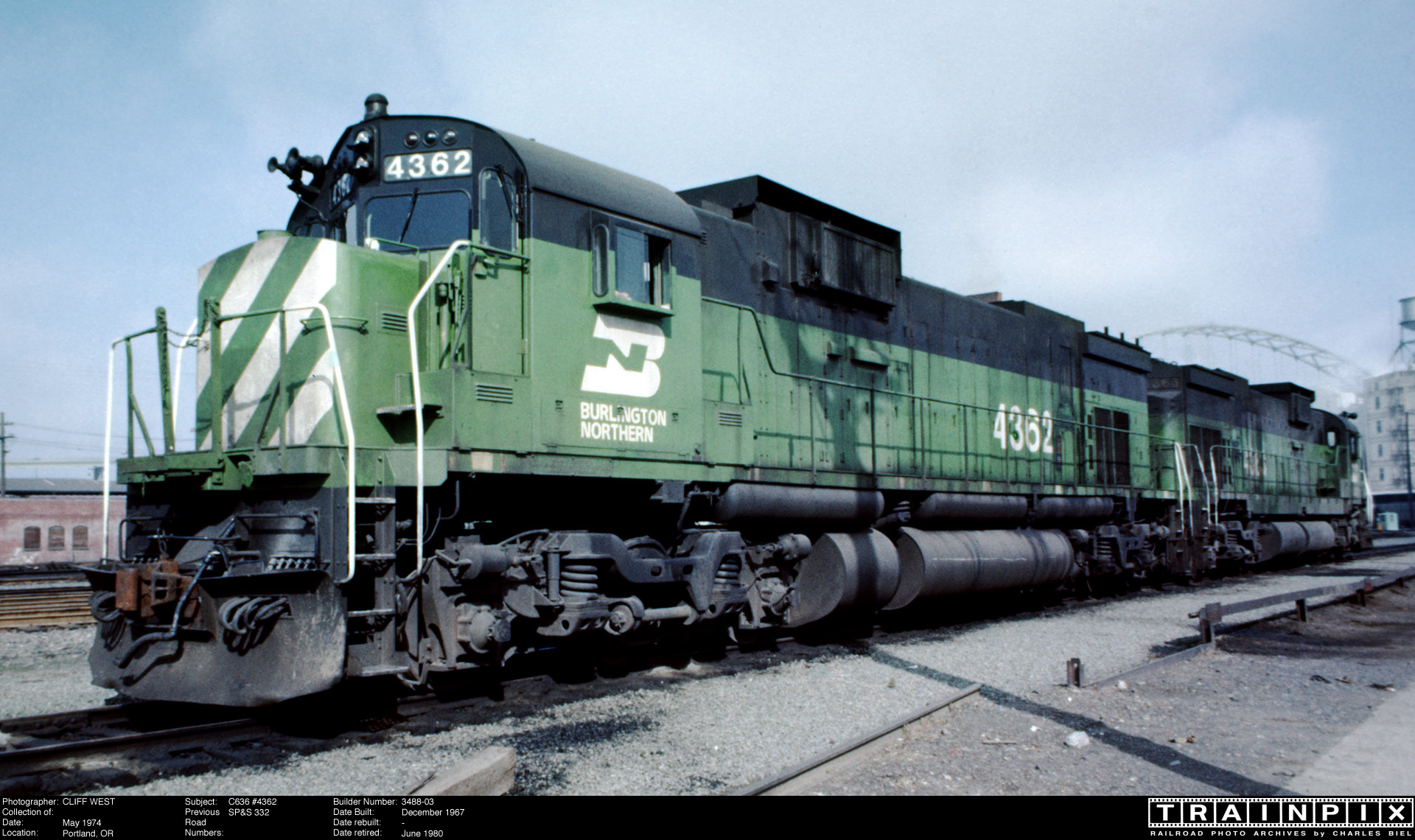 and here:  But note that the "dual radius" curve is only evident at the end plate of the fuel tank. The side of the tank is a single radius. The fuel tank is made up of several volumes. At the center, there is a rectangular box. On the sides are semi-cylindrical volumes. The height of the semi-cylinders is LESS than the height of the box. Thus the bottom of the box hangs lower than the bottom of the cylinders. The end plates smooth out this offset. I think they do that so as to reinforce the joints at that point. This feature doesn't show up on the Bowser model. Nor does it show up on my OMI models. Nor on my Alco Models model. And probably not on any others. It could be recreated rather easily and non-destructively. If anyone goes to visit a C-636, it would be a "really good thing" to photograph these end plates. Ed |
|
|
|
Post by bnsf971 on Oct 10, 2014 8:29:03 GMT -8
I am probably oversimplifying again, but why not simply file or mill off a little material from the top of the blocks on the trucks? That would lower the entire engine, and no parts would be needed.
|
|
|
|
Post by Mark R. on Oct 10, 2014 8:59:41 GMT -8
I am probably oversimplifying again, but why not simply file or mill off a little material from the top of the blocks on the trucks? That would lower the entire engine, and no parts would be needed. For anyone who likes this kind of work, that definitely looks like the answer. As for the fuel tank, now that I've seen a good shot - a 1/16" piece of styrene attached to the bottom the same size as the "box" portion of the tank, along with a properly shaped end plate made from shim brass would correct that as well. The RTR crowd aren't going to be pleased, but for anyone who actually enjoys building / modifying, it would be a fun project. Mark. |
|
|
|
Post by edwardsutorik on Oct 10, 2014 9:01:37 GMT -8
I am probably oversimplifying again, but why not simply file or mill off a little material from the top of the blocks on the trucks? That would lower the entire engine, and no parts would be needed. Certainly an option, though it's gonna take some VERY CAREFUL FILING. One could also use a mill, of course. It looks like the piece is a separate add-on piece. I wonder if it might just snap off. Then a thinner piece could replace it. If'n I went that route, I'd build a jig so that these new pieces would be dead flat with the truck--assuming the new ones would be glued on. Ed |
|
|
|
Post by edwardsutorik on Oct 10, 2014 9:09:06 GMT -8
Mark's fuel tank idea should, once the 1/16" lowering is done, bring the fuel tank close to specs. I wonder about using 1/16" brass, instead of styrene. You'll pick up about .7 ounce. If loco weight is your thing.
Ed
|
|
|
|
Post by markfj on Oct 10, 2014 9:22:33 GMT -8
OK..I think I see the problem with the tank. After looking at several pics in my Wither's six axle book, I noticed that the profile is off at the bottom. Take a true circle and cut it in half and you have the profile on the Bowser model. Take that same half but increase the tangent towards the bottom..you've got the real engine. I guess the easiest way to say this is to take a quarter circle of 18" radius track and add it to a quarter circle of 22" radius track; with the 22 at the bottom of the half circle. JL Vancouver WA I can see what is being described here:  and here:  But note that the "dual radius" curve is only evident at the end plate of the fuel tank. The side of the tank is a single radius. The fuel tank is made up of several volumes. At the center, there is a rectangular box. On the sides are semi-cylindrical volumes. The height of the semi-cylinders is LESS than the height of the box. Thus the bottom of the box hangs lower than the bottom of the cylinders. The end plates smooth out this offset. I think they do that so as to reinforce the joints at that point. This feature doesn't show up on the Bowser model. Nor does it show up on my OMI models. Nor on my Alco Models model. And probably not on any others. It could be recreated rather easily and non-destructively. If anyone goes to visit a C-636, it would be a "really good thing" to photograph these end plates. Ed Ed, very good photos and I think you hit on a valid point; the center “box” portion of the tank protrudes lower than the diameter or height of the semicircular sides. And, more importantly, the endplates hide this feature. The endplate shape is clearly visible on 4363 and you can also see the “box” bottom. That would explain why in some photos the perceived bottom of the tank is in the same horizontal plane as the pedestal jaw straps and other photos it looks like it isn't. The bottom of the box probably is in line with jaw straps, but the bottom of the curved side portion is not. We just can’t see everything clearly in the photos of the prototypes due to the shadow of the semicircular sides. Thanks, Mark |
|
|
|
Post by bigblow69 on Oct 10, 2014 9:33:06 GMT -8
Here are some shots from the C636 I cracked open, showing the truck assembly and kingpin. As I mentioned earlier, my hi-ad C630 rides at a nearly identical height to my C636, and the parts (including the frame) look identical. So, I don't think there's any change in the height or frame/truck assembly from the C630 to the C636. You can clearly see the block atop the truck gearcase that forms the truck bolster. This is the part that seems that it might be a relatively easy fix. While I had 'er cracked open I also took a shot of the motor since there were questions earlier about that. Not sure if you can tell much by a picture, but here it is. 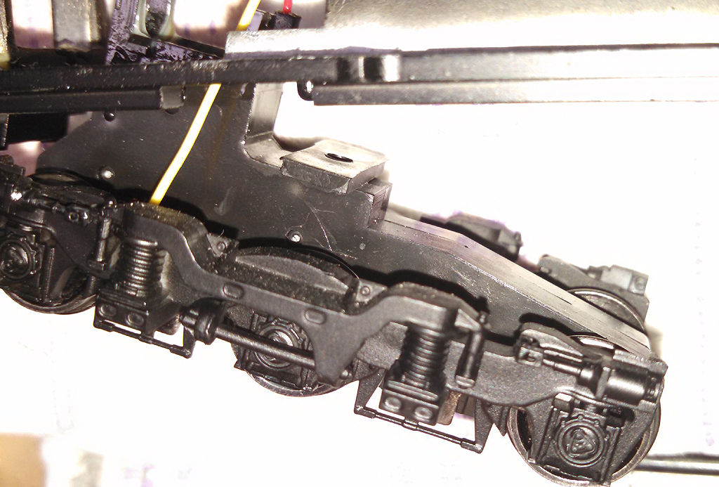 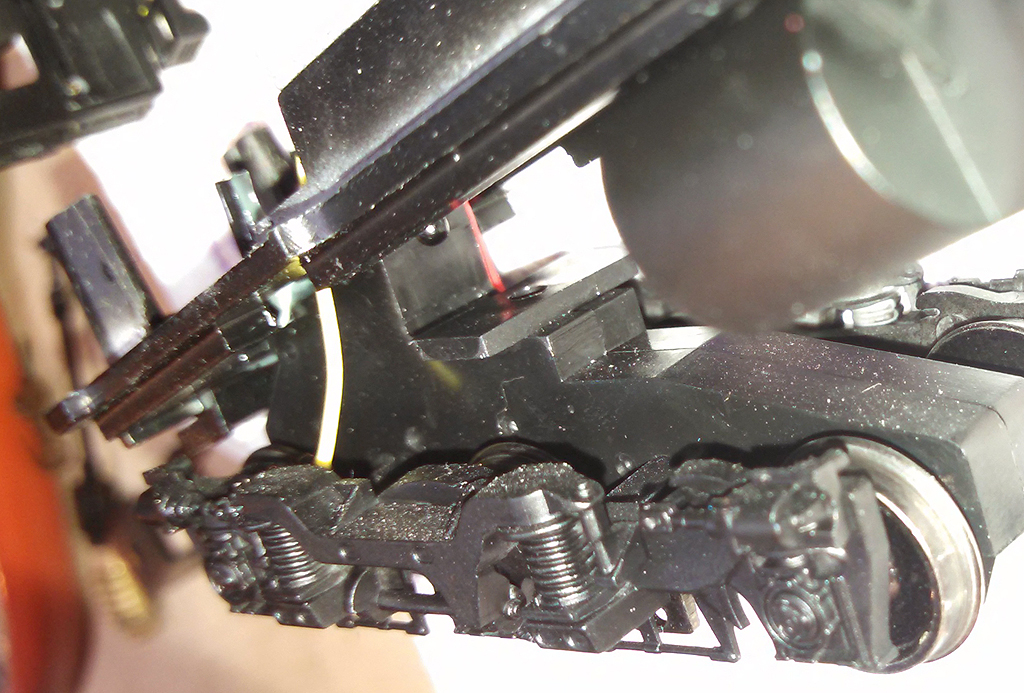 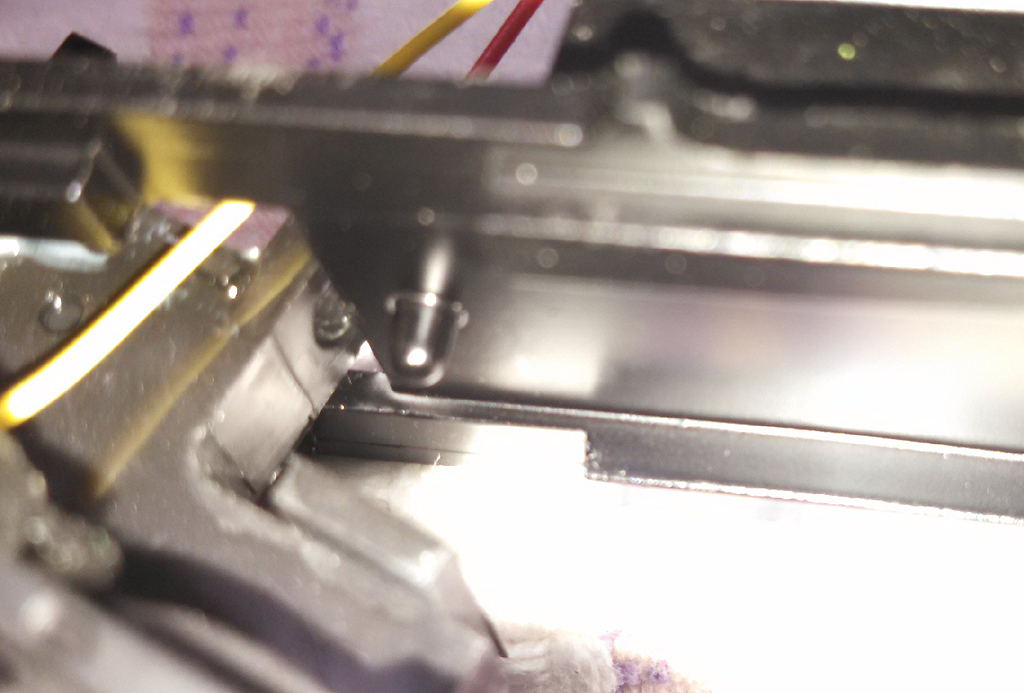 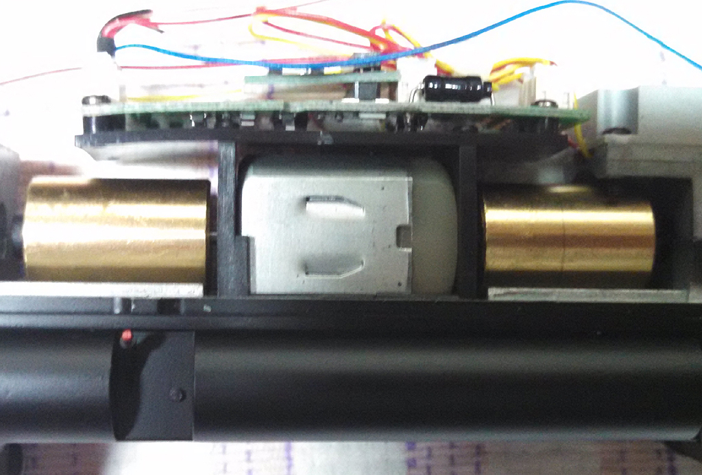 Well I'm gonna wait and see. If someone does this I'd like to see the results. I wonder if it will hurt operational performance. Don't get me started on that motor though. You would have to add material on the topside for the worm gear covers. |
|
|
|
Post by grabbem88 on Oct 10, 2014 9:45:58 GMT -8
That little block on the truck looks like they over shot it or did in conscious mind that the RTR guys will run it as is figuring most have tight radius and left some material for the prototype fellas can work it down to get it closer to spec and not worried of short radius curves..  Easy fix for us that have mills but free hand or a whoops and the trucks will be trash |
|
|
|
Post by kcjones on Oct 10, 2014 9:58:02 GMT -8
Getting back to the "tinplate" issue, this could be a compromise to get the unit to run on tight curves aka short wheelbase on Athearn's sd40-2. It seems that after 8 pages no one has found any faults in the body other than the IC class light issue. A proto tank would probably get torn up on grade crossings and the such. Lower the body and you will have clearance issues with the trucks. This of course would restrict it to 28" radius curves or greater. I have 24" on my layout and am still peeved that I can't run an Athearn DDA40X without hitting anything. But I won't complain because it doesn't look right anyway. I remember in the good ol days, that if you bought brass you had better have a layout big enough to run it on. Prototype models meant prototype curves and clearances. Other than the tank and height problem, I think it is just about perfect. If somebody builds an aftermarket tank that hugs the rail better, I can live with the rest.
JL
Vancouver WA
|
|
|
|
Post by ambluco on Oct 10, 2014 10:06:00 GMT -8
This was mentioned in a 10/7 post. the center “box” portion of the tank protrudes lower than the diameter or height of the semicircular sides. |
|
|
|
Post by Judge Doom on Oct 10, 2014 11:15:27 GMT -8
That little block on the truck looks like they over shot it or did in conscious mind that the RTR guys will run it as is figuring most have tight radius and left some material for the prototype fellas can work it down to get it closer to spec and not worried of short radius curves..  Easy fix for us that have mills but free hand or a whoops and the trucks will be trash Actually that top square area is probably normal for all recent Bowser C6xx trucks, it provides a wider area for the frame to rest on than the smaller area of the truck towers. The exact same square of the same thickness is present on the C630M - it's molded onto one of the split truck gearboxes. However, the C630M doesn't have the raised square area underneath it, part of the main truck gearboxes, which probably helps boost the height for the hi-ad truck units. |
|
|
|
Post by kcjones on Oct 10, 2014 11:31:43 GMT -8
OK.. Goofy question? If the end plate is the only issue with the tank, then why does the whole tank appear to protrude out more than a 630 tank does?
|
|
|
|
Post by Mark R. on Oct 10, 2014 12:03:45 GMT -8
OK.. Goofy question? If the end plate is the only issue with the tank, then why does the whole tank appear to protrude out more than a 630 tank does? Different size fuel capacities ? ....   Mark. |
|
|
|
Post by nightmare0331 on Oct 10, 2014 12:08:51 GMT -8
I have a mill, so I figure lowering the unit a tad is a 40 minute project.
I wonder how easily that motor could be replaced with a Kato motor.
Now I just have to convince myself I really need one.
Enjoy!
Kelley.
|
|
|
|
Post by nsc39d8 on Oct 10, 2014 12:18:11 GMT -8
I believe everyone is finally seeing the larger radius at the bottom of the tank. I have a set of Tri-mounts that I will work with and check the fit of some Hi-ADs side frames on them. Here are two photos from DL 3642. One thing no one has seen is the chain guide for the brakes. The prototype is bent/curved up to the body at the end and not straight like the model. I believe this shows some of the height problem. While I was at the DL shop I took several photos of 3642 and 3000 a M636. I detail shot most of 3642. So take a look at these two.   James Wall Rural Hall, NC |
|
|
|
Post by Judge Doom on Oct 10, 2014 12:27:49 GMT -8
I have a mill, so I figure lowering the unit a tad is a 40 minute project. I wonder how easily that motor could be replaced with a Kato motor. Now I just have to convince myself I really need one. Enjoy! Kelley. Someone over on the Diesel Detailer board posted a thread on converting a C630 to use a Kato motor. The process is probably the same for a C636. |
|
|
|
Post by Spikre on Oct 10, 2014 12:41:36 GMT -8
 Bessemer , in Your pic of 4368 the following unit is a C424,not a C425. SP&S had both C424s and C425s. note the Top Mounted Stantions, and no Radiator bulge. N&W,PRR/PC and EL also had the C424 and C425 Combination. Spikre 
|
|
|
|
Post by thebessemerkid on Oct 10, 2014 12:48:46 GMT -8
|
|
|
|
Post by thebessemerkid on Oct 10, 2014 13:01:24 GMT -8
 Bessemer , in Your pic of 4368 the following unit is a C424,not a C425. SP&S had both C424s and C425s. note the Top Mounted Stantions, and no Radiator bulge. N&W,PRR/PC and EL also had the C424 and C425 Combination. Spikre  mea culpa My vision of C424's is tainted by seeing Reading Phase 1 424's on summer visits to grandma.  When I don't see that rear overhang, I default to 425.  I think the first RR photo I took was a RDG 424, sometime in the 60's. Still have it, somewhere... |
|